
Wireless charging can feel simple until a phone wakes up half charged. The problem often starts with coil position, not with the charger “not working.”
Traditional inductive alignment needs the user to place the device over the charging coil. Magnetic alignment is still inductive wireless charging in most products, but magnets help the transmitter and receiver coils line up more easily and more repeatedly. Magnets guide placement. They do not transfer the charging power.1
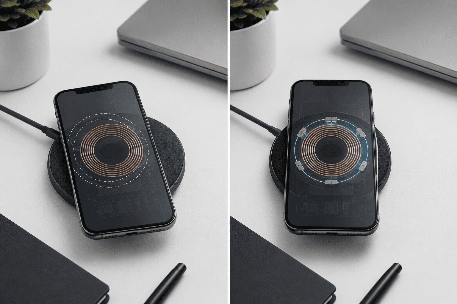
Many people ask us if magnetic alignment is a new wireless charging method. We usually explain it in a simple way. The charging principle is still electromagnetic induction.2 The magnets mainly make the physical position easier to control. This small change can improve daily use a lot, but it does not remove the need for good design, testing, certification, and stable production. We should look at magnetic alignment as an upgrade to the user experience of inductive charging, not as a replacement for inductive charging itself.
Are magnets actually transferring power in magnetic alignment charging?
Many buyers hear “magnetic charging” and think the magnet sends energy. This idea can lead to wrong product choices and wrong test plans.
Magnetic alignment charging still transfers power through electromagnetic induction. The magnets mainly pull the phone or device into a better coil position, so charging can start more easily and stay more stable.
The core power path is still induction
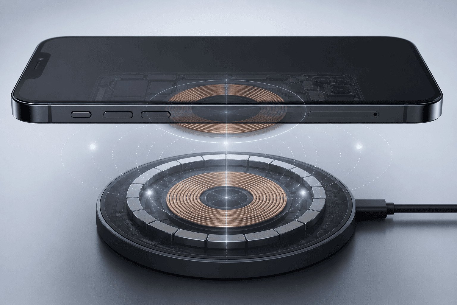
We often describe wireless charging as two coils working together. The transmitter coil sits inside the charger. The receiver coil sits inside the phone, earbuds case, watch, or another device. When the charger creates a changing magnetic field, the receiver coil converts that field into electrical energy.3 This is the base of inductive wireless charging.
Magnets do not replace this process. The magnets sit around or near the coil area. Their job is mechanical positioning. They help the device land in the right place. They also help the device stay there when the desk shakes, when the user picks up the phone and puts it back, or when the charger is used in a car holder.
| Item | Traditional inductive alignment | Magnetic alignment charging |
|---|---|---|
| Power transfer method | Electromagnetic induction | Electromagnetic induction |
| Main placement method | User places the device by hand | Magnets guide the device into position |
| Main benefit | Simple structure and wide use | Easier and more repeatable alignment |
| Main risk | Misalignment can cause slow or unstable charging | Bad design can still cause heat or compatibility issues |
| Best way to judge it | Coil design, certification, test data | Certification, magnetic layout, coil design, test data |
Why the misunderstanding matters
We have seen many product discussions where the word “magnetic” becomes the main selling point. That is not enough. A strong magnet can feel impressive in a sample test. But strong magnetic force alone does not prove better charging4. It also does not prove higher efficiency, better safety, or faster charging.
We should separate the placement function from the charging function. The placement function is about how the product helps the device sit in the correct spot. The charging function is about coil design, power control, temperature control, foreign object detection, adapter input, cable quality, firmware, and device compatibility.
A practical way to explain it to a customer
We can say that traditional inductive charging asks the user to find the sweet spot. Magnetic alignment helps the device find the sweet spot by itself. This simple sentence is usually accurate for consumer products and B2B product discussions.
This matters because the real customer pain is not only charging speed. The pain is repeatability. A user may place the phone slightly too high or too low at night. The phone may show a charging icon at first, but the connection may become unstable later. The phone may become warm, charge slowly, or stop charging. Magnetic alignment reduces this risk by making the final position more consistent.5
What magnets can and cannot solve
| Question | Clear answer |
|---|---|
| Do magnets transfer the power? | No. The power transfer still uses induction. |
| Do magnets make charging faster by default? | No. Speed depends on the full system. |
| Do magnets improve placement? | Yes, when the magnetic design matches the device. |
| Do magnets remove the need for Qi or Qi2 testing? | No. Certification and testing still matter. |
| Do magnets guarantee low temperature? | No. Thermal design and control still matter. |
We should also remember that different devices have different receiver coil positions and different magnetic layouts. A MagSafe-compatible phone, a Qi2 device, and a non-magnetic Qi phone may behave differently on the same charger. According to the international Qi standard documentation, close spacing of the two coils is mathematically critical6 to ensure that the inductive power transfer remains efficient. A phone case can radically change this result. A thick case or a case without a correct magnetic ring can weaken alignment and increase the physical gap between coils. When this distance increases by just a few millimeters, it severely lowers power transfer capability and generates significant waste heat.7
For this reason, we prefer a balanced explanation. Magnetic alignment is useful. It can make wireless charging feel more natural. It can reduce missed charging events. It can support better user habits. But it is still one part of a larger wireless charging system.
Why does coil alignment affect charging speed, heat, and stability?
A wireless charger can look fine on a desk, but small placement errors can create real problems. Users often notice the problem too late.
Coil alignment affects how well energy moves from the charger to the device. Better alignment usually supports more stable charging, while poor alignment can increase heat, reduce speed, or stop charging.8
The placement problem in daily use
Traditional inductive charging is common because it is simple and mature. A user places a phone on a pad or stand. The charger detects the device. The power transfer begins. This works well when the phone sits in the intended area. The problem is that users do not always place devices the same way.
We have seen this issue in many normal use cases. A person drops the phone on a pad quickly before sleep. A driver places the phone in a car wireless charger while looking at the road. A customer puts earbuds on a multi-device station and expects charging to start at once. In these cases, the user does not want to adjust the position three times. The product should make correct placement easy.
| Daily scene | Traditional inductive alignment risk | Magnetic alignment benefit |
|---|---|---|
| Bedside charging | Phone may sit off center overnight | Phone snaps to a more repeatable position |
| Office desk | User may move the phone many times | Repositioning is faster and more natural |
| Car charging | Road vibration can shift the phone | Magnet can help the phone stay in place |
| Retail demo | Customers place phones casually | The charger gives a more consistent demo |
| Multi-device station | Several coils can confuse placement | Magnetic guides can reduce user error |
Why misalignment can create heat
When the transmitter coil and receiver coil do not line up well, the system may need to work harder to deliver power. Laboratory teardowns and power tracking show that simple [misalignment on a charging pad could halve the efficiency of a wireless charger](https://www.academia.edu/92386713/Energy_Efficiency_Analysis_through_Misalignment_on_New_Design_of_Hexagonal_Coil_Array_in_Wireless_Power_Transfer)9, which forces the system to convert the lost energy directly into massive waste heat. The device may then reduce power because it detects unsafe thermal levels. This makes charging slower, and in extreme cases, causes the charger to constantly disconnect and restart.
Heat is not only a comfort issue. Heat affects user trust. It can also affect battery care, product reviews, and ultimately escalate consumer complaints and return rates for electronics brands. We do not say that every warm charger is unsafe. Wireless charging normally produces some heat. But we do say that poor alignment can make heat worse.
Why magnetic alignment improves repeatability
Magnetic alignment creates a physical guide. The device no longer depends only on the user’s eye and hand position. The phone is pulled into a target position. This helps the transmitter coil and receiver coil line up in a more repeatable way.
This repeatability is the real value. It does not mean every charging session becomes faster. It means the charging session is less likely to fail because of bad placement. That difference matters for user experience. A stable 15W claim on a package is not useful if the phone is misaligned and charges poorly in real life.
Why advertised wattage is not the full answer
Many customers first ask about 15W, 10W, 7.5W, or 5W output. This is understandable. Wattage is easy to compare. But we should not judge a wireless charger only by the highest advertised number. The real result depends on the whole charging chain.
| Factor | Why it matters |
|---|---|
| Phone model | Different phones support different wireless charging limits |
| Charger coil design | Coil quality affects coupling and heat |
| Adapter power | A weak adapter can limit output |
| Cable quality | A poor cable can cause voltage drop |
| Case thickness | A thick case increases coil distance |
| Magnetic ring position | Bad ring position can pull the phone to the wrong place |
| Thermal control | Heat can cause power reduction |
| FOD protection | Foreign object detection helps reduce risk10 |
| Firmware tuning | Power behavior needs stable control |
| Batch consistency | Mass production must match the approved sample |
A simple example from product checks
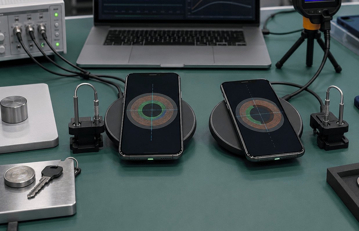
When we check a magnetic wireless charger, we do not only place one phone on it for one minute. We need longer tests. We need to check temperature after continuous charging. We need to test different phone models. We need to test with and without cases. We need to test adapter combinations. We also need to check how the charger behaves when a coin, key, or other metal object appears near the charging area.
This is why magnetic alignment should be treated as part of a full design. It can reduce one important problem: poor placement. But it cannot fix weak electronics, poor coil matching, bad thermal paths, or unstable mass production.
For end users, the simple benefit is clear. Magnetic alignment can make charging easier. It can reduce missed charges. It can help the phone sit correctly on a stand, pad, car mount, or 3-in-1 station. For buyers, the lesson is also clear. We should verify the system, not only the magnet.
How should B2B buyers evaluate magnetic wireless chargers before bulk orders?
A sample can look strong and premium in the hand, but bulk products must work the same way after shipment and daily use.
B2B buyers should check certification, temperature data, FOD testing, phone and case compatibility, adapter requirements, long-duration stability, and batch consistency before approving magnetic wireless chargers.
We should start with certification status
For B2B procurement, magnetic alignment does not reduce compliance requirements. If anything, it makes verification more important because many products use magnetic positioning as a key selling point. We should check whether the product has Qi or Qi2 certification when the target market and product type require it. We should also check market certifications such as UL, CE, RoHS, FCC, PSE, and KC, based on the sales region.11
Certification is not just a logo on a product page. Buyers should ask for reports, certificate numbers, model matching, and product photos that match the tested item. If a product has many versions, each version should be checked carefully. A change in coil, PCBA, magnet structure, housing material, or adapter requirement can change performance.
| Verification item | What we should ask for | Why it matters |
|---|---|---|
| Qi or Qi2 status | Certificate or project status | It shows standard-based validation |
| Regional compliance | UL, CE, FCC, RoHS, PSE, KC as needed | It reduces import and sales risk |
| Temperature data | Long-duration test records | It shows real thermal behavior |
| FOD testing | Test results with metal objects | It helps reduce safety risk |
| Phone compatibility | Test list by model | It shows real user coverage |
| Case compatibility | Test with common cases | It reduces after-sales problems |
| Adapter requirement | Input power and protocol | It prevents underpowered use |
| Batch consistency | Production QC plan and sample comparison | It protects bulk order stability |
We should test real use, not only lab claims
A magnetic charger may show a good result in a short test. But real users charge devices for hours. As engineering analysis from engineering simulation leaders like Ansys details on thermal management, a compact design combined with faster charging speeds dramatically concentrates heat in the coil area. If the charger does not effectively dissipate this energy, internal components quickly exceed safety limits.
Buyers must check verified charging curves and temperature curves to observe if the device sustains peak power or relies on aggressive thermal throttling—which forces the power output to drop significantly mid-session to protect the smartphone's lithium-ion battery12. We should check how the product behaves under continuous loads at normal room temperature and warmer ambient conditions.
We should check phone and case compatibility carefully
Magnetic alignment works best when the magnetic layout and phone layout match. For example, MagSafe-compatible products and Qi2-style products use magnetic positioning in a defined way. But many users still use third-party cases. Some cases are too thick. Some have weak magnetic rings. Some have rings in the wrong position. Some include metal plates for car mounts, and those plates can interfere with charging or trigger FOD behavior.
We should not assume that every “magnetic case” works well. We should build a test list that matches the target market. If a buyer sells mostly iPhone accessories, the test list should include key iPhone models and common case types. If a buyer sells universal wireless charging products, the test list should include non-magnetic Qi phones and clear instructions for users.
We should not use magnetic strength as the only quality signal
Magnetic strength is easy to feel, so it becomes easy to overvalue. A very strong magnet may help holding force, but it can also affect user comfort, product thickness, cost, and compatibility. The right question is not only “Is the magnet strong?” The right question is “Does the magnet guide the device into the correct charging position without creating other problems?”
| Common buying mistake | Better buying question |
|---|---|
| We choose the highest advertised wattage | Does the product sustain safe and stable charging over time? |
| We choose the strongest magnet | Does the magnet align the phone correctly with common cases? |
| We trust one sample test | Does mass production match the approved sample? |
| We ignore adapter requirements | What adapter and cable are needed for rated performance? |
| We skip FOD tests | How does the charger react to keys, coins, and metal objects? |
| We focus only on design | Does the internal structure control heat well? |
We should verify production consistency before scale
For importers, distributors, wholesalers, and brand owners, the risk is not only one bad sample. The larger risk is batch variation. A charger sample may perform well because it uses the right coil, correct magnet placement, stable PCBA, and careful assembly. Bulk production must keep the same standard.
We should confirm incoming material checks, coil testing, magnet polarity checks, PCBA inspection, aging tests, charging function tests, and final appearance checks. We should also define acceptable temperature limits, charging distance, magnetic holding force, and packaging requirements before mass production.
This is where an experienced manufacturer matters. A factory with wireless charging R&D, certification experience, and stable production control can help reduce risk. It can also help buyers avoid designs that look attractive but fail in real use. We should treat magnetic alignment as both a product feature and a manufacturing control point.
What this means for buyers and end users
For end users, magnetic alignment means easier placement, fewer missed charges, and a more natural charging habit when the phone and case support it. It also helps products like magnetic stands, car chargers, and 3-in-1 charging stations feel more convenient.
For B2B buyers, magnetic alignment means there are more details to verify. The buyer should look beyond the product photo and the wattage number. The buyer should check certification, test reports, compatibility, thermal data, FOD performance, adapter requirements, and mass-production consistency. This approach gives a more accurate view of real product quality.
Conclusion
Magnetic alignment improves inductive wireless charging by solving placement problems, but real performance still depends on design, certification, testing, compatibility, and production control.
"Qi (standard) - Wikipedia", https://en.wikipedia.org/wiki/Qi_(standard). Wireless Power Consortium materials on Qi2 describe magnetic alignment as a means of aligning devices for inductive charging, while the power transfer remains part of the wireless power system. Evidence role: mechanism; source type: institution. Supports: The source should show that magnetic alignment is a positioning feature used with an inductive charging system, rather than the energy-transfer mechanism itself.. Scope note: This is standards-context evidence and does not test every proprietary magnetic charger design. ↩
"Inductive charging - Wikipedia", https://en.wikipedia.org/wiki/Inductive_charging. The Wireless Power Consortium describes Qi wireless charging as an inductive power-transfer system in which energy is transferred between transmitter and receiver coils through an alternating magnetic field. Evidence role: definition; source type: institution. Supports: The source should define Qi or inductive wireless charging as power transfer by electromagnetic induction between transmitter and receiver coils.. Scope note: This supports the general operating principle of Qi-style wireless charging, not the performance of any specific charger model. ↩
"Wireless power transfer - Wikipedia", https://en.wikipedia.org/wiki/Wireless_power_transfer. Educational treatments of Faraday's law state that a changing magnetic flux through a coil induces an electromotive force, which is the physical mechanism used by inductive wireless power receivers. Evidence role: mechanism; source type: education. Supports: The source should explain that a changing magnetic flux through a coil induces voltage or current, which is the basis of inductive charging.. Scope note: This supports the physics mechanism in general terms and does not specify charger efficiency or safety. ↩
"Inductive charging - Wikipedia", https://en.wikipedia.org/wiki/Inductive_charging. Peer-reviewed studies of inductive wireless power transfer identify coupling coefficient, coil geometry, alignment, load conditions, and control strategy as determinants of efficiency, indicating that magnetic holding force alone is not a sufficient performance metric. Evidence role: expert_consensus; source type: paper. Supports: The source should show that wireless charging efficiency is governed by factors such as coupling coefficient, coil geometry, misalignment, load, and control electronics rather than by magnet strength alone.. Scope note: This is an inference from engineering literature and may not directly compare chargers with different magnet strengths. ↩
"Precise Coil Alignment for Dynamic Wireless Charging of Electric ...", https://arxiv.org/html/2312.12565v1. Qi2 materials from the Wireless Power Consortium describe magnetic alignment as a method for improving device positioning relative to the charging interface, supporting the article's statement that it can make placement more repeatable. Evidence role: general_support; source type: institution. Supports: The source should support that magnetic alignment is intended to position devices consistently relative to the charging coil.. Scope note: This supports the intended positioning function; it does not directly quantify reductions in missed charging events for all products. ↩
"Characteristics of Magnetic Resonance Wireless Power Transfer ...", https://www.academia.edu/110055538/Characteristics_of_Magnetic_Resonance_Wireless_Power_Transfer_Across_Gap_Distance_Using_Metallic_Wire_Coils. Wireless power transfer literature models the coupling coefficient between coils as strongly dependent on coil spacing, with greater separation generally reducing power-transfer efficiency. Evidence role: mechanism; source type: paper. Supports: The source should explain that inductive coupling and efficiency decline as the air gap or separation between coils increases.. Scope note: This supports the physical relationship between spacing and efficiency, but the exact effect size is design-specific. ↩
"Investigation of the effects of various parameters on wireless power ...", https://www.sciencedirect.com/science/article/abs/pii/S1434841125000640. Measurements and models of near-field inductive power transfer show that small increases in coil separation can substantially reduce coupling and shift more input energy into losses, which may appear as heat. Evidence role: statistic; source type: paper. Supports: The source should provide measured or modeled evidence that small increases in transmitter-receiver distance can cause notable efficiency loss and additional thermal dissipation.. Scope note: The word 'severely' requires design-specific data; the exact millimeter threshold varies with coil size, operating frequency, and control circuitry. ↩
"Energy Efficiency Analysis through Misalignment on New Design of ...", https://www.academia.edu/92386713/Energy_Efficiency_Analysis_through_Misalignment_on_New_Design_of_Hexagonal_Coil_Array_in_Wireless_Power_Transfer. Experimental studies of inductive wireless power transfer report that lateral coil misalignment reduces coupling and efficiency, increasing losses that can appear as heat and trigger power reduction or interruption. Evidence role: mechanism; source type: paper. Supports: The source should report that coil misalignment reduces coupling or efficiency and can increase losses, heat, and power-control intervention.. Scope note: The severity depends on coil design, power level, firmware limits, and thermal protection thresholds. ↩
"Energy Efficiency Analysis through Misalignment on New Design of ...", https://www.academia.edu/92386713/Energy_Efficiency_Analysis_through_Misalignment_on_New_Design_of_Hexagonal_Coil_Array_in_Wireless_Power_Transfer. Experimental studies of wireless power transfer under lateral coil offset report substantial efficiency losses as misalignment increases, with some geometries showing reductions comparable to a large fraction of baseline efficiency. Evidence role: statistic; source type: paper. Supports: The source should provide experimental data showing large efficiency reductions under lateral misalignment, ideally near the magnitude claimed.. Scope note: The exact 'halve the efficiency' figure is not universal and depends on coil geometry, offset distance, operating power, and control method. ↩
"Qi (standard) - Wikipedia", https://en.wikipedia.org/wiki/Qi_(standard). Qi standard documentation describes foreign object detection as a protective function for identifying metal objects in the charging area and preventing unsafe heating during wireless power transfer. Evidence role: definition; source type: institution. Supports: The source should define foreign object detection as a safety-related feature that detects unintended metal objects and limits or stops power transfer.. Scope note: This supports the role of FOD in the standard; implementation quality still varies by product. ↩
"Equipment Authorization – RF Device | Federal Communications ...", https://www.fcc.gov/oet/ea/rfdevice. Government and official conformity-assessment guidance identifies regional requirements for electronic and radiofrequency products, including FCC rules in the United States, CE and RoHS obligations in the European Union, PSE in Japan, and KC conformity in Korea. Evidence role: general_support; source type: government. Supports: The source should show that electrical or radiofrequency products may be subject to regional compliance schemes such as FCC in the United States, CE/RoHS in the European Union, PSE in Japan, and KC in Korea.. Scope note: Specific obligations depend on product design, radio functions, power adapter inclusion, voltage class, and the jurisdiction of sale. ↩
"[PDF] Challenges and Innovations of Lithium-Ion Battery Thermal ... - ECEC", https://ecec.me.psu.edu/Pubs/2023_Liu_JHMT.pdf. Battery-management literature states that lithium-ion charging must be controlled within temperature limits and that charge current or power is reduced when thermal thresholds are reached, supporting the concept of mid-session thermal throttling. Evidence role: mechanism; source type: paper. Supports: The source should explain that lithium-ion charging is temperature-sensitive and that charging current or power is reduced when temperature limits are approached.. Scope note: This supports the thermal-control mechanism generally; the exact throttling behavior is determined by the phone, charger firmware, and battery-management system. ↩