
Poor alignment looks like a small issue. It can waste power, raise heat, and make buyers doubt the charger’s real performance.
Magnetic alignment reduces power waste by guiding the phone’s receiving coil closer to the charger’s transmitting coil.1 It does not create extra power. It improves coil overlap, supports stronger coupling, lowers lost energy, and helps the charger keep a more stable and efficient charging path.
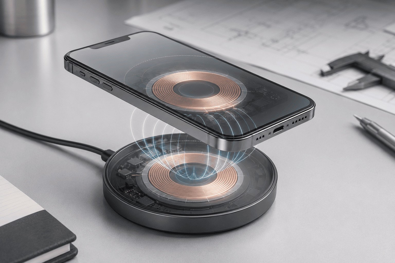
We have tested many wireless chargers in factory conditions and in daily use scenes. We have seen one clear truth. A phone that only “sticks” to a charger is not always charging well. A good magnetic wireless charger must hold the phone in the right position, control heat, work with different cases, and keep stable output during long charging sessions. This is where good engineering starts to matter.
Why Does Coil Alignment Matter in Wireless Charging?
A phone can look correctly placed. The coils may still be off-center. That small shift can waste energy and create unwanted heat.
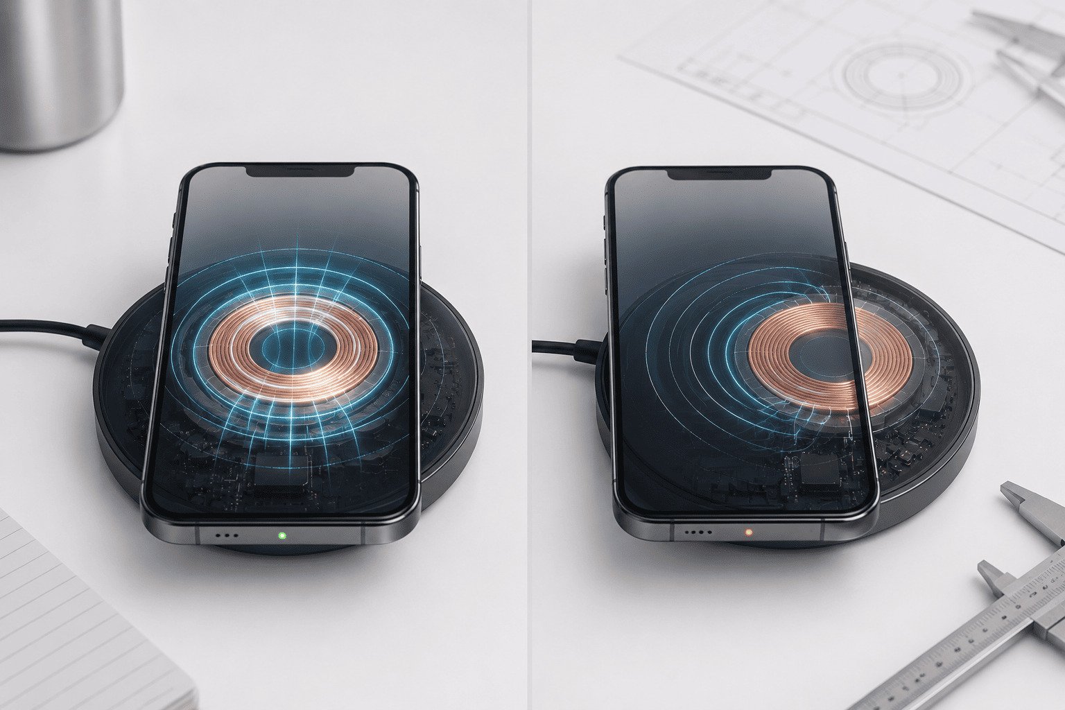
Wireless charging works best when the transmitting coil and receiving coil overlap well. Better overlap improves electromagnetic coupling.2 Poor overlap weakens energy transfer.3 The charger may draw power, but less energy reaches the phone battery. More unused energy becomes heat.4
Coil overlap is the real starting point
We often explain wireless charging with one simple image. The charger has a transmitting coil. The phone has a receiving coil. Energy moves across the air gap through an electromagnetic field.5 This process needs distance control and position control. If the phone moves away from the best spot, the coupling becomes weaker.
Magnetic alignment helps because it gives the user a repeatable placement point. The magnet layout pulls the phone toward the intended center. The user does not need to guess the correct position each time. This is useful for desktop chargers, car wireless chargers, power banks, and 3-in-1 charging stations.
| Placement condition | Coil overlap | Energy transfer | Common result |
|---|---|---|---|
| Centered position | High | More efficient | Stable charging and lower heat |
| Slight offset | Medium | Less efficient | Slower charging and warmer surface |
| Large offset | Low | Poor | Stop-start charging or FOD trigger |
| Thick case plus offset | Very low | Unstable | Heat, low speed, or no charge |
We should not say alignment solves every problem. It mainly improves the chance that the coils stay close to the designed position. That gives the charging IC and thermal system a better condition to work with.
Does Magnetic Alignment Create More Charging Power?
Some sellers make magnetic charging sound like magic. That can mislead buyers and create wrong expectations during product selection.
Magnetic alignment does not create extra charging power.6 It helps reduce wasted power by keeping the phone closer to the best coil position. Real charging speed still depends on the phone, coil design, input adapter, charging IC, thermal limits, and protocol support.7
Magnets guide position, but the system decides output
We treat magnets as a mechanical alignment tool. They help the phone land in the right place and stay there. They do not raise wattage by themselves. A stronger magnet does not automatically mean faster charging.8 A weak system with strong magnets can still charge poorly简短表述. A well-balanced system with proper magnetic force can charge more safely and more consistently.
We have seen samples that attach very firmly, but they still become hot in testing. The reason was not attachment. The reason was poor coil position, poor heat path, or weak firmware control. We have also seen samples with comfortable magnetic force that performed better because the coil, magnet ring, charging IC, and structure worked together.
| Factor | What it controls | Why it matters |
|---|---|---|
| Magnet layout | Phone position and holding force | It affects repeatable alignment |
| Coil position | Coupling quality | It affects power transfer efficiency |
| Charging IC | Power control | It manages protocol, output, and protection |
| Thermal design | Heat movement | It keeps temperature within safe limits |
| Adapter input | Available power | It affects stable output headroom |
| Phone compatibility | Real receiving behavior | Different phones react differently |
We advise buyers to judge the full charging system, not only the magnet strength. A product must pass charging stability tests, temperature tests, misalignment tests, and aging tests before it is ready for mass supply.
How Does Misalignment Turn Power Into Heat?
Heat is not only a comfort issue. It can slow charging, shorten product life9, and increase after-sales risk for distributors.
When coils are misaligned, electromagnetic coupling becomes weaker. The charger may increase effort to maintain charging, but less useful energy reaches the phone. The lost energy often appears as heat in the coil, circuit board, phone back, or charger housing.
Heat shows where energy is being lost
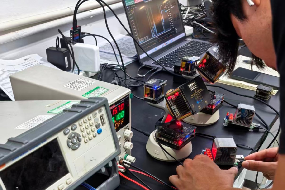
In our factory tests, temperature data often tells the real story. A charger can show normal power input, but the phone battery may not receive power efficiently. If the coils are not aligned well, part of the energy does not move cleanly from transmitter to receiver. The system then works harder. The coil, MOSFET area, shielding material, and housing may become warmer.
The phone can also lower charging power when its internal temperature rises. This means the user may see slower charging after a few minutes. The charger may be rated for a certain wattage, but the real charging curve drops because heat control fails.
| Test observation | Possible cause | Buyer risk |
|---|---|---|
| Fast heat rise in first minutes | Poor coil overlap or high loss | User complaints |
| Charging starts and stops | FOD trigger or unstable coupling | High return rate |
| Output drops after warm-up | Thermal throttling | Lower real performance |
| Hot spot near coil | Weak heat spreading | Material aging risk |
| Phone case gets very warm | Thick case or poor alignment | Safety concern |
Magnetic alignment reduces this risk by helping the phone return to the designed charging center. It does not remove all heat. It gives the full system a better chance to run within the intended range.
What Makes a Magnetic Wireless Charger Reliable in Real Use?
A lab result can look clean. Real users place phones quickly, use cases, charge in cars, and leave devices charging overnight.
A reliable magnetic wireless charger must maintain stable alignment, safe temperature, and steady power under real use conditions. This needs good coil placement, magnet design, thermal structure, firmware control, FOD protection10, certified components, and consistent mass production.
Real reliability comes from the whole design
We do not design magnetic wireless chargers only for a single perfect test. We design them for repeated use. A buyer may sell to users with different phones, different cases, and different adapters. A car charger may face vibration. A desktop charger may hold a phone at an angle for video calls. A power bank may charge while the user walks.
This is why validation must include many test points. We usually check alignment tolerance, magnetic holding force, output stability, temperature rise, standby loss, FOD response, adapter matching, and long-time aging. We also check the structure after drop tests and cable pull tests. A good sample must still perform after normal use stress.
| Real use condition | Design challenge | Validation focus |
|---|---|---|
| Thin phone case | Normal magnetic gap | Stable output and temperature |
| Thick phone case | Larger coil distance | Lower loss and safe cut-off |
| Car vibration | Position movement | Holding force and charging continuity |
| 3-in-1 station use | Multi-device heat | Total thermal control |
| Power bank use | Battery heat plus coil heat | Heat spread and protection |
| Overnight charging | Long run time | Aging and safety stability |
For procurement teams, this matters because after-sales cost often comes from small weak points. A charger may pass a quick demo, but it may fail when thousands of users use it in different ways.
How Should Buyers Evaluate Magnetic Alignment Before Bulk Orders?
A beautiful sample can hide weak engineering. Buyers need a clear test method before they approve mass production.
Buyers should evaluate magnetic alignment by checking coil centering, charging stability, temperature rise, case compatibility, FOD protection, adapter matching, and batch consistency. They should ask for test reports and compare performance across real devices, not only one ideal phone.
A practical evaluation path reduces procurement risk
We suggest buyers build a simple but strict approval checklist. First, check whether the phone snaps into a repeatable center position. Second, test charging with at least several major phone models. Third, test with common case thicknesses. Fourth, measure surface temperature after a full charging period. Fifth, check whether the charger stops safely when metal foreign objects are placed near the coil.
Buyers should also compare pilot samples with mass-production units. This step is important. A prototype can be hand-tuned. Mass production needs stable fixtures, clear process control, and incoming material checks. Magnet position, coil position, shielding position, PCB quality, and housing tolerance all affect final performance.
| Buyer checkpoint | What to ask supplier | What good performance looks like |
|---|---|---|
| Coil and magnet drawing | Position tolerance and layout | Clear design control |
| Temperature test | Test time, room temperature, phone model | Controlled rise without sharp hot spots |
| FOD test | Metal object response | Safe stop or protection action |
| Case test | Case thickness range | Stable charging within claimed range |
| Adapter test | Input power requirement | Stable output with recommended adapter |
| Batch test | Sample size and pass rate | Consistent results across units |
| Certification | CE, FCC, RoHS, UL, Qi, PSE, KC as needed | Market-ready compliance |
We also advise buyers to ask about production capacity and quality systems. A supplier should control both design and output. At Fabucharger, we have built wireless charging products since 2017. We work with OEM and ODM projects. We use factory tests, certification support, and mass-production checks to reduce risk for wholesalers, importers, and brand owners.
Why Is Mass-Production Consistency So Important for Magnetic Alignment?
One good sample is not enough. A small shift in production can change alignment, heat, and charging stability.
Mass-production consistency keeps the coil, magnets, PCB, shielding, and housing in the designed positions. If these parts drift during production, wireless charging efficiency can drop. Stable tooling, inspection, and process control help every unit keep similar charging behavior.
Small tolerances can create big field differences
Wireless charging is sensitive to position. [A few millimeters can matter](https://pmc.ncbi.nlm.nih.gov/articles/PMC11161604/)11. In mass production, every part has tolerance. The coil has placement tolerance. The magnet ring has assembly tolerance. The housing has molding tolerance. The PCB has soldering and component tolerance. If these small errors add together, the final unit may charge differently from the approved sample.
This is why we pay attention to fixtures, incoming inspection, line testing, and aging. A stable factory process is not only about making enough units per day. It is also about making units that behave the same way. For B2B buyers, this affects complaints, warranty cost, and brand trust.
| Production area | Possible drift | Control method |
|---|---|---|
| Magnet assembly | Magnet ring off-center | Position fixture and polarity check |
| Coil assembly | Coil shift or tilt | Assembly jig and visual inspection |
| PCB production | Component variation | Supplier control and function test |
| Shielding material | Wrong placement | Process standard and inspection |
| Housing molding | Fit tolerance change | Tooling control and sample check |
| Final test | Hidden performance gap | Charging test and temperature sampling |
A factory with strong R&D and production control can find these issues earlier. This helps buyers avoid unstable batches. It also helps brands keep the same user experience across markets.
Conclusion
Magnetic alignment reduces power waste by improving coil overlap. Real efficiency still depends on the full charger design, validation process, and production consistency.
"Alignment-Free Wireless Charging of Smart Garments with ... - PMC", https://pmc.ncbi.nlm.nih.gov/articles/PMC8588031/. A peer-reviewed study of inductive wireless power transfer shows that lateral coil misalignment reduces magnetic coupling and transfer efficiency, supporting the statement that alignment can reduce wasted power; the study’s coil geometry may differ from specific phone chargers. Evidence role: mechanism; source type: paper. Supports: A peer-reviewed source should show that lateral alignment between transmitting and receiving coils affects coupling coefficient, transfer efficiency, and losses in inductive power transfer.. Scope note: Contextual support, because experimental coil sizes and operating conditions may not match the charger model discussed in the article. ↩
"Structure Design of Quadrilateral Overlapped Wireless Power ... - PMC", https://pmc.ncbi.nlm.nih.gov/articles/PMC9415458/. Educational treatments of mutual inductance explain that magnetic coupling depends on coil geometry and relative position, which supports the statement that better coil overlap improves coupling; this establishes the physical principle rather than measuring a particular charger. Evidence role: mechanism; source type: education. Supports: An educational or engineering source should explain that mutual inductance and coupling depend on coil geometry and relative alignment.. Scope note: Contextual support, because a general electromagnetics source does not directly test this product category. ↩
"Energy Efficiency Analysis through Misalignment on New Design of ...", https://www.academia.edu/92386713/Energy_Efficiency_Analysis_through_Misalignment_on_New_Design_of_Hexagonal_Coil_Array_in_Wireless_Power_Transfer. Research on inductive wireless power transfer reports that lateral or angular misalignment can reduce power transfer efficiency, supporting the claim that poor coil overlap weakens energy transfer; the magnitude of the effect depends on coil design and control circuitry. Evidence role: mechanism; source type: paper. Supports: A research paper should report that lateral or angular coil misalignment reduces power transfer efficiency in inductive charging systems.. Scope note: Contextual support, because efficiency loss varies by coil design, operating frequency, and compensation topology. ↩
"[PDF] COIL MISALIGNMENT COMPENSATION TECHNIQUES ... - RUcore", https://rucore.libraries.rutgers.edu/rutgers-lib/48468/PDF/1/play/. Studies of inductive wireless charging identify resistive and magnetic losses as heat sources and report that inefficient coupling can raise temperatures, supporting the statement that unused energy appears as heat; the exact heat distribution depends on materials and charger architecture. Evidence role: mechanism; source type: paper. Supports: A technical study should link lower transfer efficiency or misalignment in wireless power transfer to increased losses and thermal rise.. Scope note: Contextual support, because the source may not measure the same enclosure, shielding, or phone case conditions. ↩
"Inductive charging - Wikipedia", https://en.wikipedia.org/wiki/Inductive_charging. Reference descriptions of inductive charging define it as power transfer between coils by electromagnetic induction across a gap, supporting the article’s basic mechanism statement. Evidence role: definition; source type: encyclopedia. Supports: An encyclopedia or educational source should define inductive charging as energy transfer using electromagnetic fields between coils.. ↩
"Qi (standard) - Wikipedia", https://en.wikipedia.org/wiki/Qi_(standard). The Wireless Power Consortium describes magnetic alignment as a positioning feature within wireless charging standards, while charging power is governed by the power-transfer system and specification limits; this supports the distinction between alignment and power creation. Evidence role: definition; source type: institution. Supports: A standards source should show that magnetic features are used for alignment or positioning while power limits and transfer behavior are governed by the charging system and protocol.. Scope note: Contextual support, because standards language may define system roles without explicitly refuting every marketing claim about magnets. ↩
"[PDF] Thermal Design and Optimization of High-Power Wireless Charging ...", https://www.osti.gov/servlets/purl/1871896. Wireless charging standards and device guidance indicate that delivered charging power depends on transmitter and receiver capabilities, supported power profiles, input supply, and thermal management, supporting the article’s multi-factor explanation of charging speed. Evidence role: expert_consensus; source type: institution. Supports: A standards or technical source should show that delivered wireless charging power depends on receiver capability, transmitter capability, negotiated protocol, and safety or thermal controls.. Scope note: Contextual support, because no single standards source may discuss every listed component in the same terms. ↩
"Wireless power transfer - Wikipedia", https://en.wikipedia.org/wiki/Wireless_power_transfer. Standards discussions of magnetic wireless charging treat magnets as an alignment aid, while charging power is controlled by transmitter-receiver design and protocol limits, supporting the statement that stronger magnets alone do not ensure faster charging. Evidence role: general_support; source type: institution. Supports: A standards or technical source should support the distinction between magnetic attachment or alignment and the electrical factors that determine charging power.. Scope note: Contextual support, because the source may not directly compare products with different magnet strengths. ↩
"Heat Generation and Degradation Mechanism of Lithium-Ion ... - PMC", https://pmc.ncbi.nlm.nih.gov/articles/PMC9753165/. Battery-aging and electronics-reliability research shows that elevated operating temperature can accelerate degradation and reduce service life, supporting the article’s warning that heat can shorten product life; the degree of aging depends on chemistry, design, and usage profile. Evidence role: expert_consensus; source type: research. Supports: A research or government source should show that elevated temperature accelerates battery aging or reduces electronic component reliability.. Scope note: Contextual support, because the source may address batteries or electronics generally rather than a specific wireless charger. ↩
"Qi (standard) - Wikipedia", https://en.wikipedia.org/wiki/Qi_(standard). Wireless charging standards describe foreign object detection as a protective function for identifying metal objects that may heat in the charging field, supporting the article’s inclusion of FOD as a reliability and safety checkpoint. Evidence role: definition; source type: institution. Supports: A standards institution should describe foreign object detection as a feature or requirement intended to detect metal objects and reduce heating risk.. Scope note: Contextual support, because implementation quality and test thresholds vary by product and certification scope. ↩
"Design and implementation of a high misalignment-tolerance ... - PMC", https://pmc.ncbi.nlm.nih.gov/articles/PMC11161604/. Experimental studies of inductive wireless power transfer report measurable reductions in coupling or efficiency from small lateral coil offsets, supporting the claim that a few millimeters can affect charging behavior; the threshold depends on coil diameter and system design. Evidence role: mechanism; source type: paper. Supports: A study should report measurable changes in coupling coefficient, efficiency, or power transfer from millimeter-scale coil misalignment.. Scope note: Contextual support, because the cited measurements may use test coils that are not identical to commercial phone chargers. ↩